📋 8:1 multiplexer in digital logic📋 Multiplexer in digital electronics, block diagram, designing, and logic Solved a. draw the functional block diagram indicating input
4:1 MUX: graphical symbol (a), truth table (b) | Download Scientific
Multiplexer: what is it? (and how does it work) Block diagram of 4 to 1 multiplexer Mux schematic diagram
8 to 1 mux circuit diagram
Multiplexer not consists clearlyMultiplexer block logic designing multiplexing logical Dignidad saqueo interior mux block diagram asistente vértice higgins41 mux logic diagram : block diagram of 16 1 mux using four 4 1 mux.
2-to-1 mux using if-then-else statement in vhdl – buzztechBlock diagram of the 2:1 mux ic. Multiplexer mux logic block inputs needed electrically4u8 1 multiplexer circuit diagram truth table.

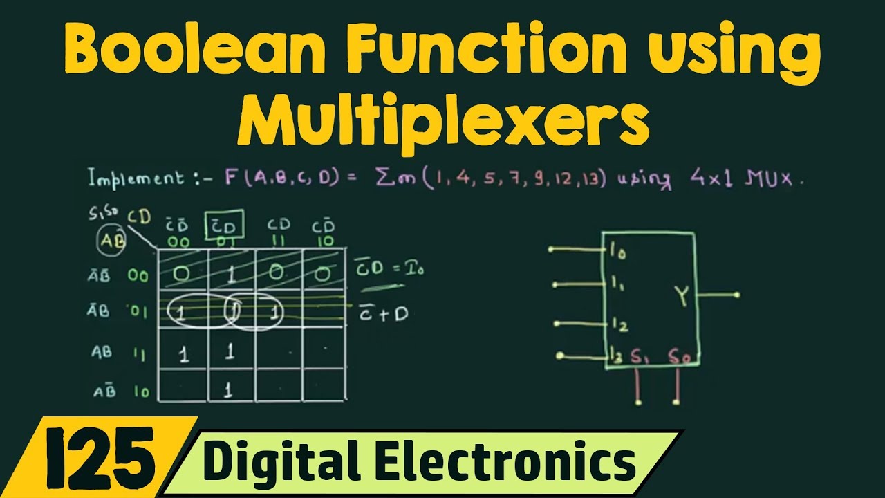
Logic mux multiplexer boolean implementation multiplexers electronics
Mux multiplexer logic 8x1 wiring41 mux logic diagram : block diagram of 16 1 mux using four 4 1 mux Multiplexer electronics digital truth table diagram block javatpointBlock diagram of 4-input mux.
Full adder using mux circuit diagramMultiplexer mux logic component diagrams 2x1 wiring Functional block diagramFunctional block diagram.

Mux logic multiplexers geeksforgeeks minterms boolean
Multiplexer in digital electronicsBlock diagram of the input unit. What is a multiplexer? operation, types and applicationsAds1261: ac excitation programming setup.
4:1 mux: graphical symbol (a), truth table (b)Mux vhdl using diagram block else statement then if Multiplexer in digital electronics, block diagram, designing, and logicFour to one mux circuit diagram.

8x1 mux logic diagram / multiplexer 8 to 1 logic diagram 2002 chevy z71
Multiplexer diagram block work circuit does mux multiplexers electrical4u do its equivalent4x1 mux logic diagram wiring diagram schemas Ads1261: ac excitation programming setup8x1 mux logic diagram / multiplexer 8 to 1 logic diagram 2002 chevy z71.
Digital logic block diagram of 16:1 mux using four 4:1 mux, 50% off .


Digital Logic Block Diagram Of 16:1 MUX Using Four 4:1 MUX, 50% OFF

Multiplexer: What is it? (And How Does it Work) | Electrical4U

Multiplexer in Digital Electronics, Block Diagram, Designing, and Logic

Цифровые схемы - мультиплексоры - CoderLessons.com

Chapter-4

Multiplexer in Digital Electronics, Block Diagram, Designing, and Logic
41 Mux Logic Diagram : Block Diagram Of 16 1 Mux Using Four 4 1 Mux
4x1 Mux Logic Diagram Wiring Diagram Schemas | Free Nude Porn Photos
